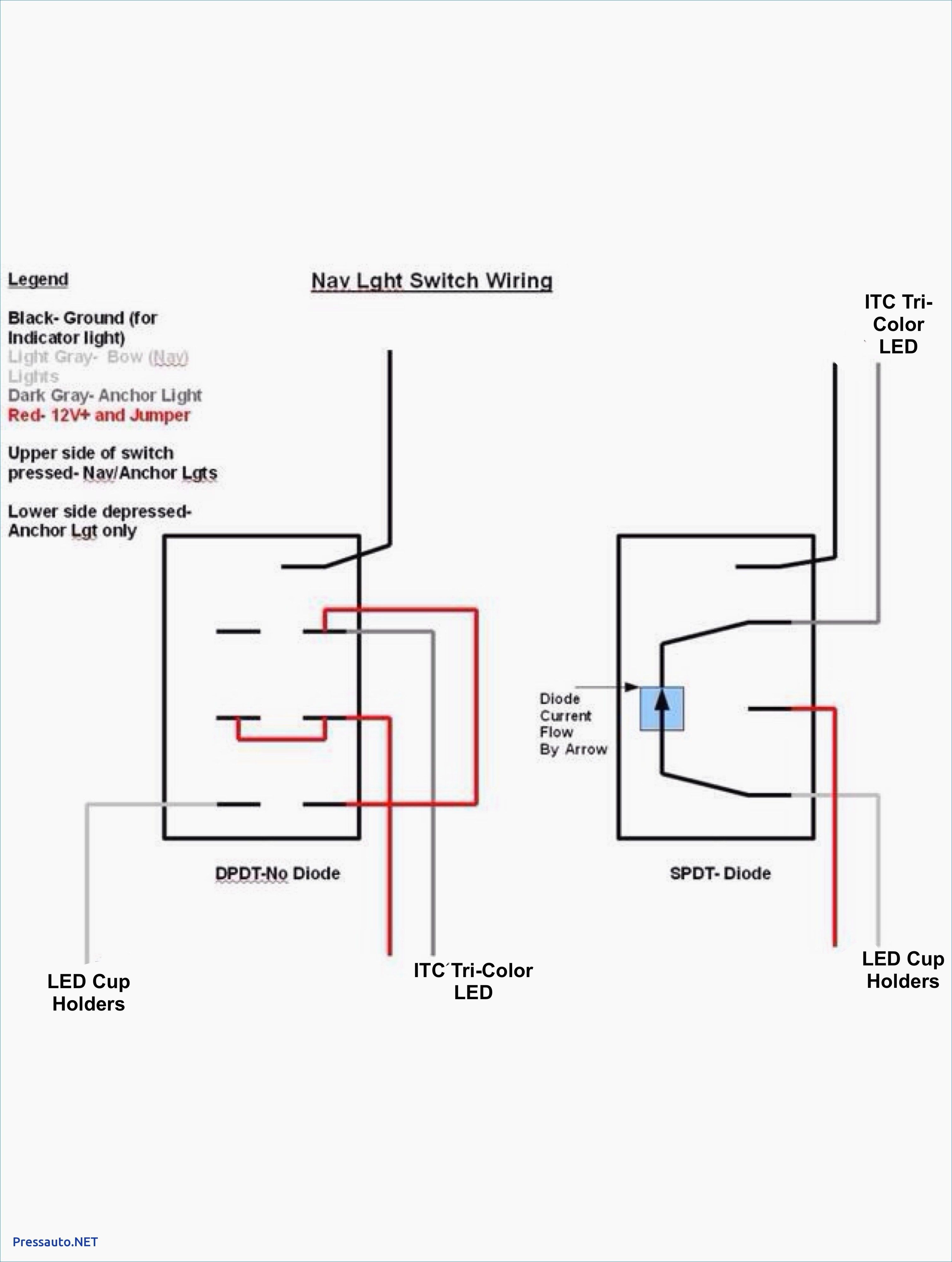
Supreme Dpdt Toggle Switch Wiring Diagram

Below is the schematic diagram of the wiring for connecting a dpdt toggle switch.
Dpdt toggle switch wiring diagram. We will now go over the wiring diagram of a dpdt toggle switch. They are mechanically coupled. Look at the figure 1 2 the centre dotted line indicates that the dpdt switch is actually two spdt switches in one package.
Dpdt double pole double throw toggle. Terminals 3 and 4 represent the toggle switch. A dpdt toggle switch has 6 terminals.
Dpdt toggle switch wiring. So if a fan is connected to terminal 1 and a motor is connected to. In this video i give you the character.
A double pole double throw toggle switch is a combination of two individual spdt single pole double throw switches connected in the single assembly. These terminals receive the power necessary to drive the loads on terminals 1 and 5 and 2 and 6. This is how you wire a double pole double throw dpdt switch.
2 methods are explained with associated wiring diagrams.


